Step 2Bb: Nudged Elastic Band (NEB) Calculations
Tip
Download the template folder for this step by clicking the button below and work on the files in the template folder as you read through this tutorial.
In an NEB, we trace a path from the reactant to the product. An optimisation is performed across all the images at the same time in order to try to find the transition step.
Note
The NEB process is a bit more involved compared to the other steps.
The general steps for performing an NEB calculation are:
- Choose an optimised structure and modify it.
- Optimise the modified structure with constraints (optional, but recommended).
- Optimise the modified structure without constraints.
- Double-check the reactant and product structures.
- Perform the Climbing Image - Nudge Elastic Band (CI-NEB) calculation.
Step 2Bb.1: Choose an Optimised Structure and Modify it
To begin, it is a good idea to take either the optimised Reactant or Product structure from Step 1. Then, move the relevant atoms in the structure of the Reactant (Product) so that it resembles the Product (Reactant) somewhat.
- The reason for doing this is to make sure any atoms not involved directly in the mechanism are:
- Ordered correctly for NEB calculations, and
- To try to keep these atoms in the same position as best as possible.
- The reason for doing this will be clearer once we perform the NEB calculation in Step 2Bb.5.
Tip
Once you have moved the atoms in your modified structure, make sure the modified atoms are fairly close to each other. This is because ORCA (as well as any DFT program) can have trouble optimising structures where atoms are initially far away from each other.
- As a rule of thumb, any atoms you have modified that are bonded to eachother should be about ~0.5 Å - ~0.75 Å apart. It is easier for ORCA to increase bond lengths during optimisations rather than decrease them.
In this example below, I have chosen the Product structure to focus on. I then moved atom 17 (Cu) to the other side of the N atom (atom 12), and moved atom 16 (H) down so that it was close to the C atom (atom 11).


Step 2Bb.2: Optimise Reactant from Product (or Product from Reactant) With Constraints (Optional but Recommended)
Next, we perform a geometric optimisation calculation on this modified structure. However, we don't want the atoms that are not involved in the mechanism to move.
- To achieve this, we constrain the atoms in the molecule that are not involved in the mechanism.
In this example, we will optimise the newly created reactant structure. Here, we have chosen to constrain the atoms in the benzene moiety from moving. The orca.inp file for this example is given below (also located here):
!B3LYP DEF2-TZVP D3BJ
!OPT FREQ TightOPT TightSCF defgrid2
%SCF
    MaxIter 2000       # Here setting MaxIter to a very high number. Intended for systems that require sometimes 1000 iterations before converging (very rare).
    DIISMaxEq 5        # Default value is 5. A value of 15-40 necessary for difficult systems.
    directresetfreq 15 # Default value is 15. A value of 1 (very expensive) is sometimes required. A value between 1 and 15 may be more cost-effective.
END
%CPCM EPSILON 6.02 REFRAC 1.3723 END
%PAL NPROCS 32 END
%maxcore 2000 # This indicates you want ORCA to use only 2GB per core maximum, so ORCA will use only 2GB*32=64GB of memory in total.
%GEOM
    Constraints
        {C 0 C}
        {C 1 C}
        {C 2 C}
        {C 3 C}
        {C 4 C}
        {C 5 C}
    END
END
* xyzfile 1 1 reactant.xyz
The optimisation of this constrained molecule is shown below (ase gui orca_trj.xyz or viewORCA opt):
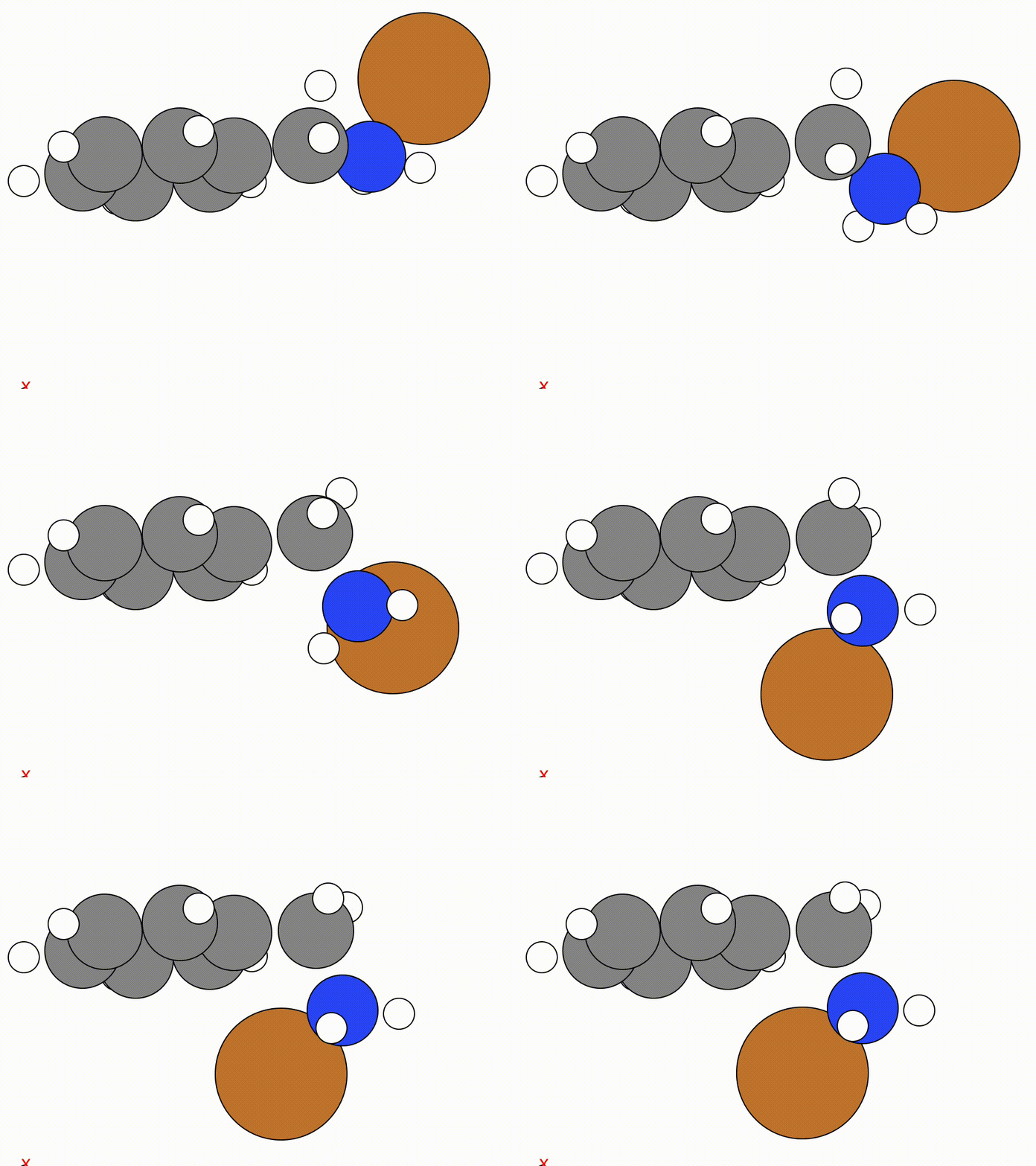
By constraining the benzyl atom in benzylamine, we have allowed the Cu atom to optimise to an ideal position while keeping the benzyl moiety in the same place.
Note
This is an optional step as we perform another geometric optimisation step in Step 2Bb.3.
- The reason for this contrained geometric optimisation step is because it makes it easier to view the structural change from our reactant to product structures and confirm both the reactant and product structures are in fact the structures we want to investigate the mechanistic step for.
- While this step is optional, it is highly recommended to perform this constrained optimisation job before performing a unconstrained geometric optimisation in Step 2Bb.3, as it makes it easier to check you are happy with your reactant and product structure before performing the NEB calculation.
Step 2Bb.3: Optimise Reactant from Product (or Product from Reactant) Without Constraints
Now that we have optimised the constrained reactant, we now repeat the optimisation process above, but without the constraints.
- We do this to make sure that this structure is absolutely in a local minimum.
- We do not expect the atoms in this molecule to move much, as the atoms we contrained were from an already optimised structure.
The ORCA input file here as the same as in Step 2Bb.2, excluding the Constraints component. The orca.inp file for this example is given below (also located here):
!B3LYP DEF2-TZVP D3BJ
!OPT FREQ TightOPT TightSCF defgrid2
%SCF
    MaxIter 2000       # Here setting MaxIter to a very high number. Intended for systems that require sometimes 1000 iterations before converging (very rare).
    DIISMaxEq 5        # Default value is 5. A value of 15-40 necessary for difficult systems.
    directresetfreq 15 # Default value is 15. A value of 1 (very expensive) is sometimes required. A value between 1 and 15 may be more cost-effective.
END
%CPCM EPSILON 6.02 REFRAC 1.3723 END
%PAL NPROCS 32 END
%maxcore 2000 # This indicates you want ORCA to use only 2GB per core maximum, so ORCA will use only 2GB*32=64GB of memory in total.
* xyzfile 1 1 reactant_opt_constrained.xyz
In this example, the unconstrained optimisation calculation does not change the molecule much, which is what we ideally want.
IMPORTANT
If you find the atoms have changed position significantly compared to that in Step 2Bb.2, this is a problem.
- If this happens, you likely need to go back to Step 1 and make sure your original structure is geometrically optimised.
Step 2Bb.4: Double-Check the Reactant and Product Structures
Before beginning the NEB calculation, it is a good idea to perform some double checks on your reactant and product structures. These checks have already been mentioned, but it is worth mentioning them again. There are:
- Make sure you are happy with your input reactant and product structures, and
- Make sure the atom index ordering between your input reactant and product structures are as expected (i.e. the same).
To help perform these two checks, use the ase gui as follows:
-
Change directory into the folder containing the NEB calculation, as open both your optimised reactant and products in
ase gui: -
Next, in the ASE GUI click
View->Show Labels->Atom Index. This will display the indices of the atoms in your reactant and product structures. -
Flick between the reactant and product structures and check that the structures of the reactant and product are:
- As expected (i.e. look like the reactant and product you want to understand the mechanistic step for).
- Have the same index ordering.
Example
In the example below,
- The reactant and the product look like the mechanism we described in the first mechanistic step iun the Before You Begin step, and
- We see that the atom indices for each atom in the reactant and product align with each other, such that there is a natural way to get from reactants to products.
So we are happy


Step 2Bb.5: Perform the Climbing Image - Nudge Elastic Band (CI-NEB) Calculation
In an NEB, we trace a path from the reactant to the product. An optimisation is performed across all the images at the same time in order to try to find the transition step.
In the .inp file, you want to include the following:
The tags here indicate you want to do the following:
NEB-CI: This keyword will perform a nudged-elastic band (NEB) calculation upon your system using the climbing image (CI) varient of the NEB algorithm.TightSCF: Tells ORCA to tighten the convergence criteria for each electronic step.defgrid2: Indicates how fine we want the intergration grid to be (This is the default).
We also include the following NEB settings:
%NEB
    NEB_END_XYZFILE "product_opt.xyz"
    Nimages 100
    Interpolation IDPP
    Opt_Method LBFGS
END
* xyzfile 1 1 reactant_opt_unconstrained.xyz
The tags here indicate you want to do the following in your NEB calculation:
NEB_END_XYZFILE: This is the reactant structure you want to use. Include this file in the same place as your ORCA.inpfile.Nimages: These are the number of images you want to include in the NEB calculation (not including the reactant and product image).- In this example, we will create 102 images from
reactant_opt_unconstrained.xyztoopt_product.xyz(100 images in between but not includingreactant_opt_unconstrained.xyztoopt_product.xyz)
- In this example, we will create 102 images from
Interpolation: This is the interpolation scheme first used to create all the initial images.Opt_Method: This is the optimisation method used.
IMPORTANT
It is important that the atom ordering in your reactant and product xyz files are the same, otherwise you will problems where atoms seems to move about in nosense ways. If you have check this during Step 2Bb.4, you should be all good to go.
NOTE 1
In this example I have set Nimages to 100. I chose this to allow for some smoothness between images in the mechanistic step. However, you could set this to much less and everything would probably work. For example, 20 would probably also work fine.
- Try not to use too many images, as this can cause problems and also increases the amount of time required for the NEB to converge.
NOTE 2
I use LBFGS in this example as the optimisation method. This is a very good algorithm, but it can be a bit loose and cause issues. In testing I tried the FIRE method, This worked also, but causes jitters which can lead to problems.
- The point is if you have convergence problems, try using another method for
Opt_Method. - See the ORCA manual 6.1.0: Page 651 for options for this setting.
In this example, we are looking at how a Cu atom could insert itself into a C-H bond. The full orca.inp file is given below (also located here):
!B3LYP DEF2-TZVP D3BJ
!NEB-CI TightSCF defgrid2
%SCF
    MaxIter 2000       # Here setting MaxIter to a very high number. Intended for systems that require sometimes 1000 iterations before converging (very rare).
    DIISMaxEq 5        # Default value is 5. A value of 15-40 necessary for difficult systems.
    directresetfreq 15 # Default value is 15. A value of 1 (very expensive) is sometimes required. A value between 1 and 15 may be more cost-effective.
END
%CPCM EPSILON 6.02 REFRAC 1.3723 END
%PAL NPROCS 32 END
%maxcore 2000 # This indicates you want ORCA to use only 2GB per core maximum, so ORCA will use only 2GB*32=64GB of memory in total.
%NEB
    NEB_END_XYZFILE "product_opt.xyz"
    Nimages 100
    Interpolation IDPP
    Opt_Method LBFGS
END
* xyzfile 1 1 reactant_opt_unconstrained.xyz
Outputs from ORCA
ORCA will create a number of files, as well as the output.out file. These are the important ones to look at for NEB calculations:
orca_initial_path_trj.xyz: This is the initial NEB path that you want to investigate.orca_MEP_trj.xyz: This is the NEB trajectory for the mechanism.orca_NEB-TS_converged.xyz: This is the transition state that was obtained from this NEB calculation.
IMPORTANT: Things to do while the NEB calculation is running
Once ORCA has begun running the NEB calculation, there are two things that you should do:
- Check the
orca_initial_path_trj.xyzfile. - Check the NEB calculation daily.
Below is a description of these two checks:
1. Check the orca_initial_path_trj.xyz file
Once ORCA begins, the first step in the NEB calculation is to create all the initial images connecting the reactant and the product using an interpolation scheme.
- ORCA will create a file called
orca_initial_path_trj.xyz. This file gives an idea of the initial NEB path that ORCA will begin investigating. - Check this file in
ase guiand see that this initial mechanistic pathway look somewhat sensible.
# change directory into the folder containing your NEB calculation
cd ORCA_Mechanism_Procedure/Examples/Step2_Find_TS/Step2Bb_NEB/Step2Bb_5_Run_NEB_Calculation

# View the reactant and product for the NEB calculation using ASE
ase gui orca_initial_path_trj.xyz
Example
For this example, the orca_initial_path_trj.xyz file looks like this:
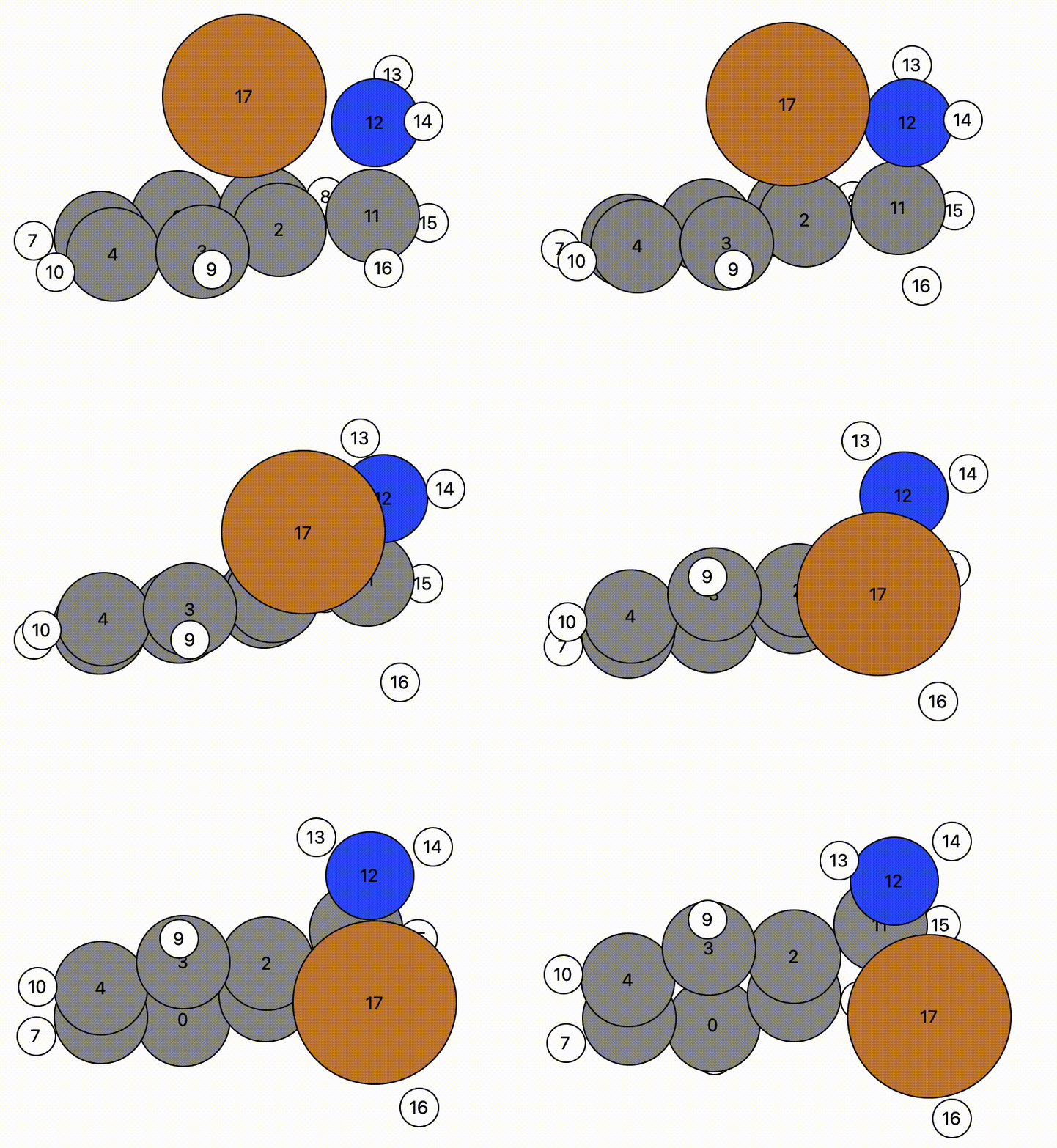
In this example, atom 16 (H) floats away in free space from atom 11 (C), and there is a bit of time before atom 16 bonds to atom 17 (Cu).
- This indicates there may be a problem and the NEB calculation might have trouble.
- However, NEB calculations are designed to change the mechanistic path to account for this and will find a more likely mechanistric pathway, so this is not a horrible initial NEB pathway.
I would be happy with this calculation to proceed as it is, but it would be wise to check this calculation daily as it runs.
Tip
The general rule is: The simplier you can make the initial NEB pathway, the more likely the NEB calculation will converge.
2. Check the NEB calculation daily
NEB calculations, like any ORCA or DFT calculation, have the potential to go in weird directions that makes convergence unlikely. This is particularly the case for NEB calculations. For this reason, it is important to do the following checks on a daily basis:
-
Check the
orca_MEP_trj.xyzfile. This file describes the current reaction pathway as calculated by NEB.- View this file by running
ase gui orca_MEP_trj.xyzin the terminal. - Hopefully the NEB path given in this file look better and better as ORCA proceeds.
- The main thing is to check that the NEB path given by
orca_MEP_trj.xyzis still sensible by your chemical intuition.
- View this file by running
-
Check the
output.logfile to make sure everything is running smoothly.- The best way to check the
output.logfile is to scroll to the bottom of theoutput.logfile. - If there are any problems, it may come up in the
output.logfile. - If you are using slurm, you should also look at the slurm output and error files to see if there are any issues reported there.
- The best way to check the
-
Check how the energy profile of the NEB calculation has changed by running the
viewORCA neb_snapcommand in your terminal.- This command will present the energy profile snapshots of all the NEB iterations that ORCA has performed thus far.
- Run this command by changing directory to the folder containing your NEB run in the terminal, and then running the
viewORCA neb_snapcommand.
# cd into your optimisation folder cd ORCA_Mechanism_Procedure/Examples/Step2_Find_TS/Step2Bb_NEB/Step2Bb_5_Run_NEB_Calculation # View the NEB calculation viewORCA neb_snap-
viewORCA neb_snapwill create two files. These are:orca_NEB_optimization.png: This file contains the plots of all the NEB optimisation iterations that have been performed so far.orca_NEB_last_iteration.png: This is the plot of the last NEB optimisation iteration.
Example
Examples of the
orca_NEB_optimization.pngandorca_NEB_last_iteration.pngfiles are shown below: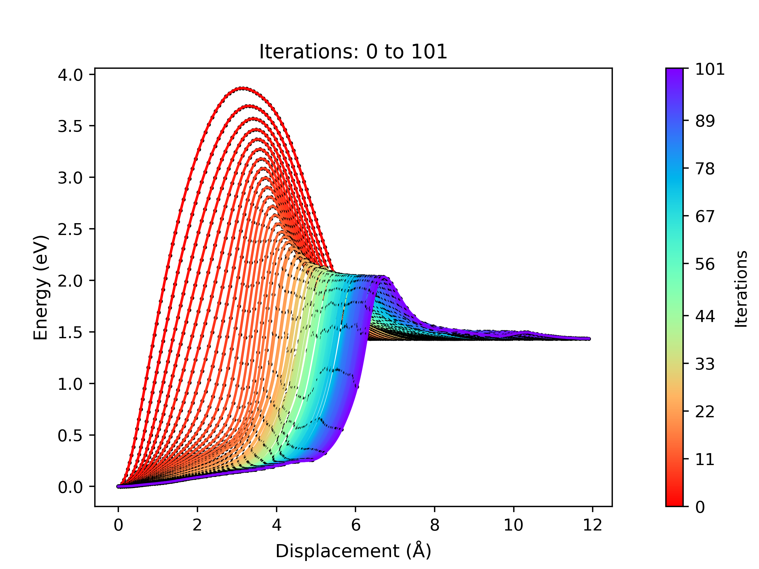
Energy profile of each NEB optimisation iteration performed by ORCA. This is given by the 'orca_NEB_optimization.png' file. 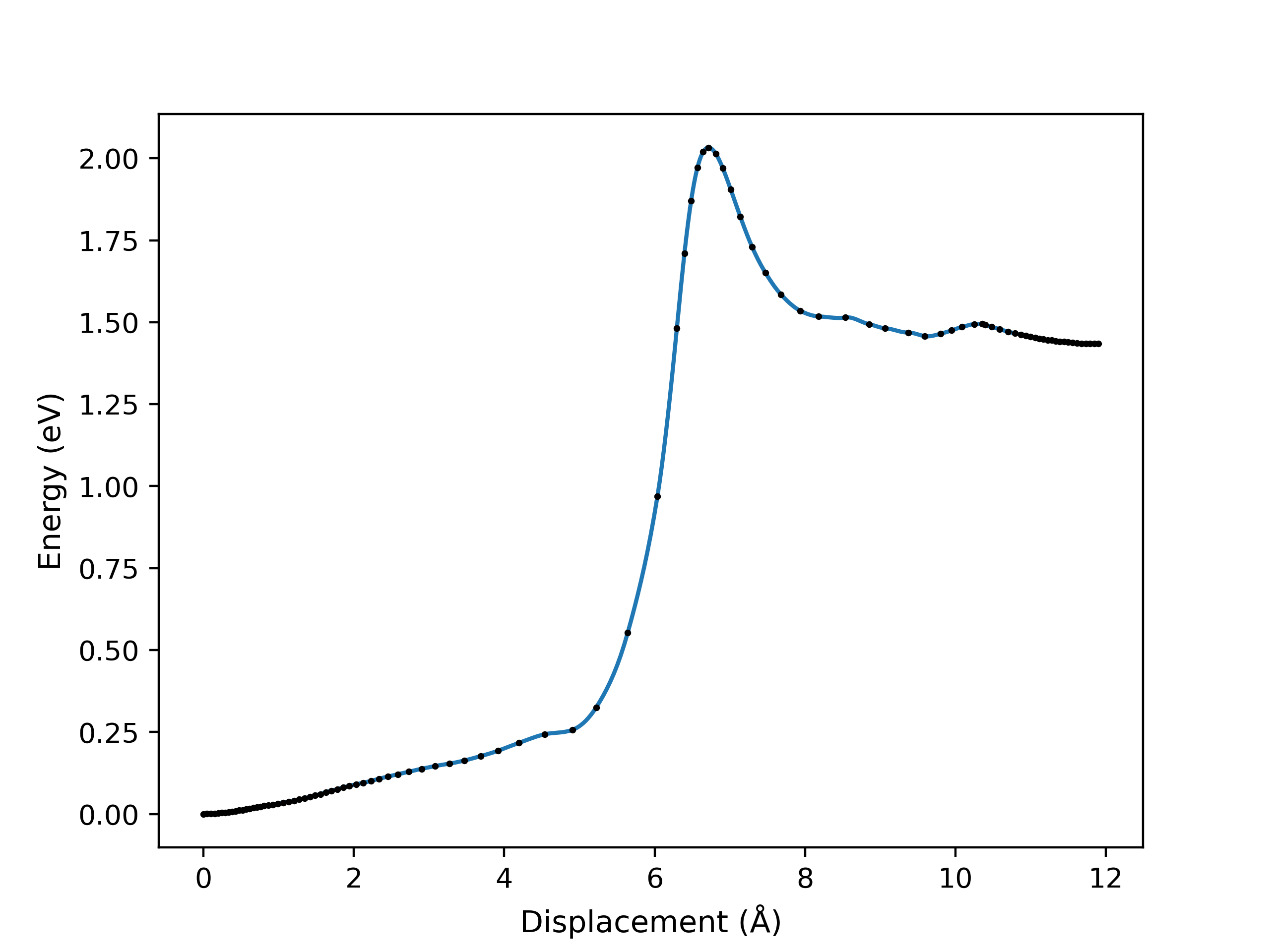
Energy profile of the last NEB optimisation iteration, as performed by ORCA. This is given by the 'orca_NEB_last_iteration.png' file.
How to analyse the output files after the NEB calculation has finished
Once ORCA has finished performing the NEB calculation, we will want to visualise the NEB. You can visualize how ORCA has performed the mechanistic step by typing viewORCA neb into the terminal.
# cd into your optimisation folder
cd ORCA_Mechanism_Procedure/Examples/Step2_Find_TS/Step2Bb_NEB/Step2Bb_5_Run_NEB_Calculation

# View the NEB calculation
viewORCA neb
You will get a GUI that shows you the following NEB pathway:
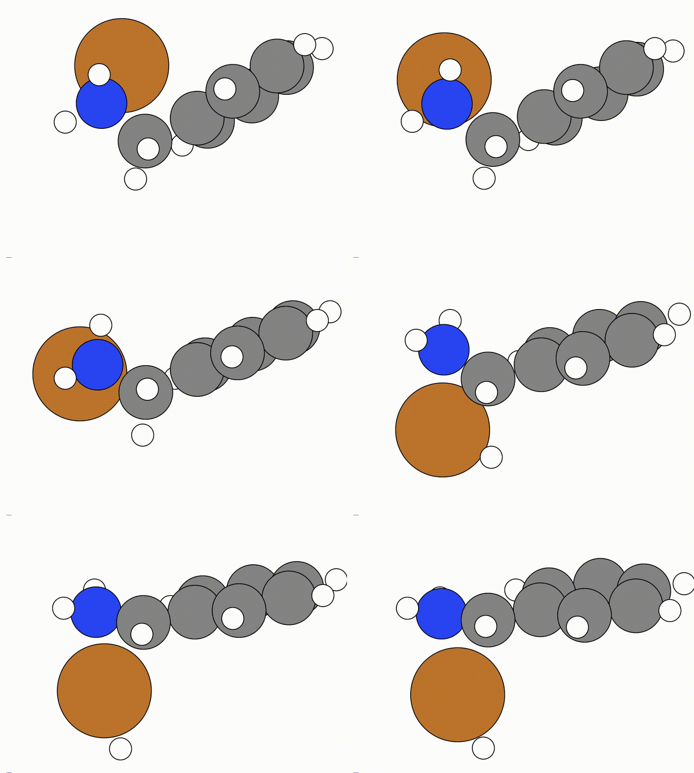
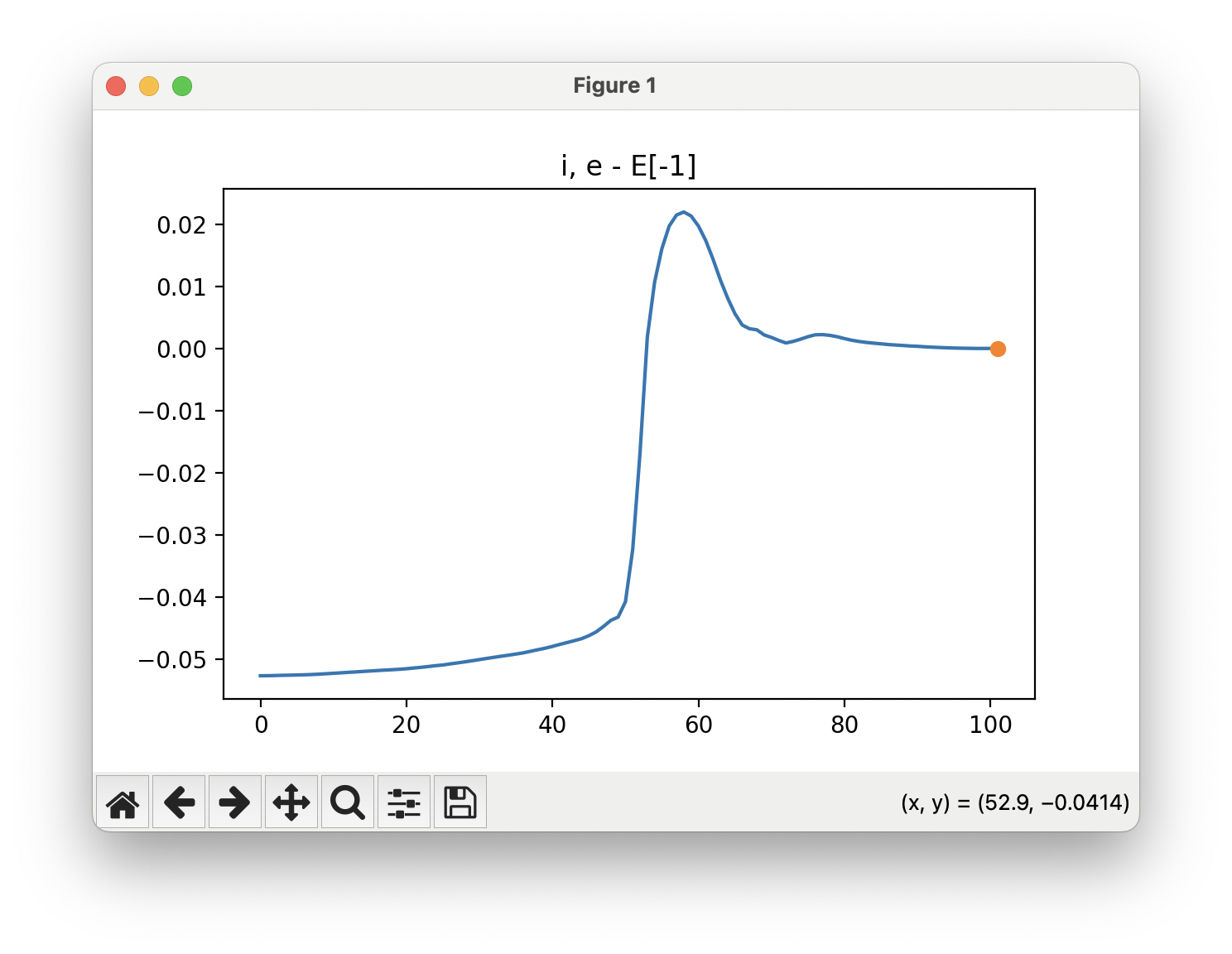
The energy profile for this example is given below:
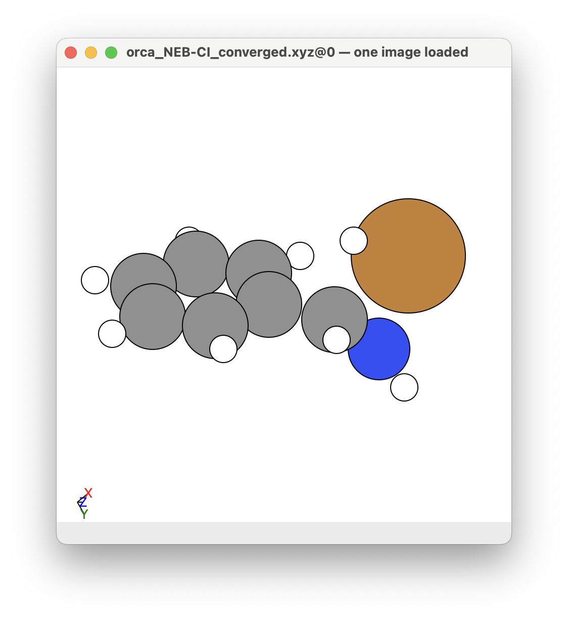
You can see that a transition state is given by ORCA as the orca_NEB-CI_converged.xyz file. This is what the given transition state looks like in this example:
Other comments about NEBs
Comments about the Opt_Method settings
The LBFGS is a common optimisation algorithm used in geometric optimisations. The note from ORCA is that The L-BFGS is more aggressive and efficient, but also more error-prone. Because of this, it is a common strategy to change the optimisation algorithm used to help the NEB calculation.
- In testing this proceedure I also used the
FIREwhich is also a good algorithm. - However in this case, the
FIREalgorithm was less able to scout the NEB. - Here is the NEB for the same NEB calculation shown above using the
FIREmethod.
This is the NEB path that I got from the NEB calculation using the FIRE algorithm:

The energy profile for this example is given below:

You can see from the NEB path and the energy profile that its a bit jittery, but overall the NEB did work as we found a good transition state:

At the end of the day, it doesnt matter how "well" the NEB calculation did, it only depends if we find a sufficient transition state that we can further optimise in Step 3: Optimise the Transition State. So I would say I would be happy with how this NEB ran, and would have continued to Step 3.
Other Information about performing NEBs in ORCA
The following links have good information for performing NEBs in ORCA:
- https://www.faccts.de/docs/orca/6.0/tutorials/react/nebts.html: Nice article from the developers about how to perform an NEB in ORCA.
- https://sites.google.com/site/orcainputlibrary/geometry-optimizations/tutorial-neb-calculations: Nice extra information for performing and analysising NEBs.
- https://github.com/via9a/neb_visualize: Contain another program for analysing how the NEB optimised. This program is really good for figuring out how the NEB optimised itself, very helpful!
Troubleshooting the Nudged Elastic Band (NEB) Calculation
Here are some troubleshooting tips for performing this optimisation step.
Also look at the following websites for help:
- https://sites.google.com/site/orcainputlibrary/scf-convergence-issues (apart of https://sites.google.com/site/orcainputlibrary)
No troubleshooting issues have been found yet.
Info
If you have any issues about this step, raise a New issue at the Issues section by clicking here.
